

Details
|
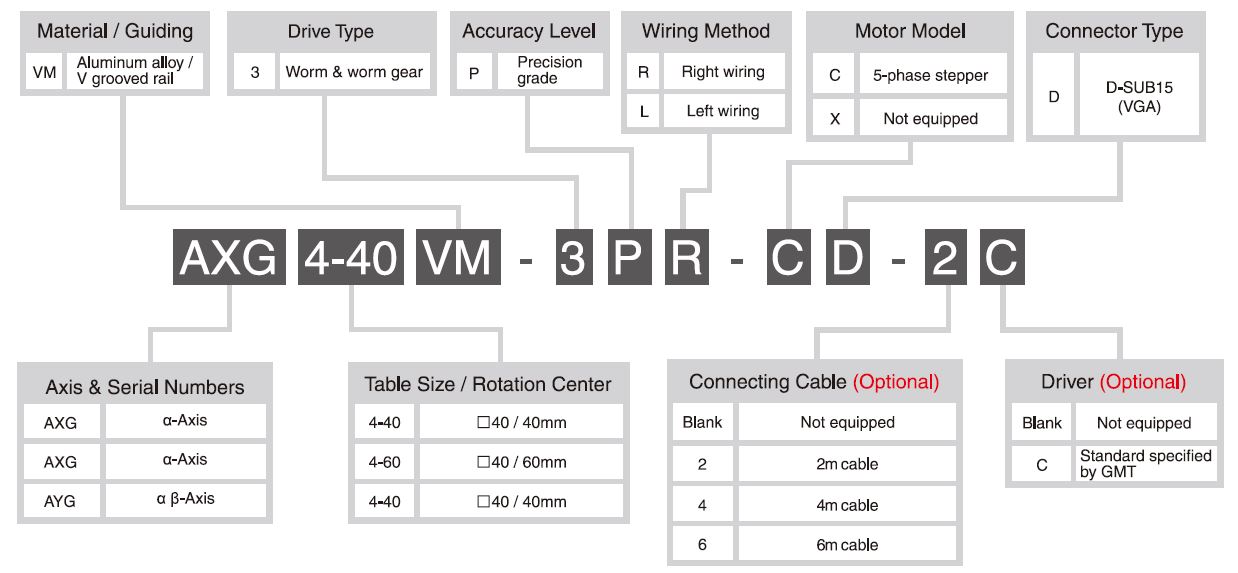
Model No. |
AYG4-40VM-3PR-CD |
||
|
Mechanical Spec. |
Table Size (mm) |
40 X 40 |
|
|
Travel Stroke (°) |
Upper Axis:± 8 Lower Axis:± 6 |
||
|
Drive Type |
Upper Axis:Worm & Worm Gear (Ratio 1 / 240) Lower Axis:Worm & Worm Gear (Ratio 1 / 335) |
||
|
Rail |
Crossed Roller Guiding |
||
|
Stage Material / Surface Treatment |
Aluminum Alloy / Black Anodized |
||
|
Main Unit Weight (Kg) |
0.82 | ||
|
Coupling |
FAMMS12-3*5 |
||
|
Accuracy Level |
P:Precision grade |
||
|
Wiring Method |
R:Right Wiring / L:Left Wiring |
||
|
Precision Spec. |
Resolution (Pulse) (°) |
Upper Axis:≒ 0.003 (Full);≒ 0.0015 (Half) Lower Axis:≒ 0.0021 (Full);≒ 0.00105 (Half) |
|
|
Max. Speed (Full Step) (° / sec) |
Upper Axis:15 Lower Axis:10.75 |
||
|
Repeatability Precision (°) |
Follow each single axis precision |
||
|
Load Capacity (Kgf) |
2.5 |
||
|
Missed Step (°) |
0.01 |
||
|
Dynamic Straightness (mm) |
40 ± 0.3 |
||
|
Dynamic Parallelism (mm) |
0.02 |
||
|
Electrical Spec. |
Motor |
Type / Shaft Numbers |
5-phase stepper / ☐ 28 double shafts |
|
Brand / Model |
SANYO / SH5281-7211 |
||
|
Driver Brand / Model |
Please refer to reference table |
||
|
Connector |
Stage Side Connector |
15-Pin male end connetor D-SUB / 12-Pin male end connetor HRS |
|
|
Controller Side Connector |
15-Pin female end connetor D-SUB / 12-Pin female end connetor HRS (Additional options) |
||
|
Sensor |
Origin Sensor |
Photoelectric sensor GMT-sensor |
|
|
Limit Sensor |
|||
|
Origin Approximation Sensor |
N / A |
||
|
Power Voltage |
24V ± 10% |
||
|
Control Output |
NPN open collector output under 24V 8mA |
||
|
Output Control |
Testing (sensing):output transistor OFF (closed) |
||
| System Configuration Diagram |
|
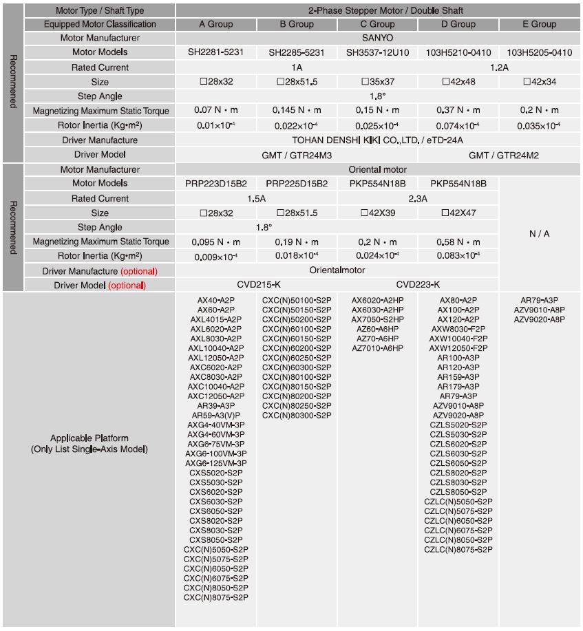
♦ For selection of the drivers preferred, please refer to the reference table or the catalogue of Motor・Driver. ♦ All of the drivers chosed are the specification of GMT preferred. For different needs, please choose the suitable drivers according to real functional needs.
|

| Axis Definition |
|
GMT has defined different axis as the following figuration according to the movement direction: Horizontal movement direction is X and Y axis. Vertical movement direction is Z axis. Movement around X, Y, Z axis is defined to α axis, β axis, and θ axis. Green arrows present the specified axis movement direction.
|

Motor・driver Reference Table |
|
|
|
|

View more about AYG4 - Precision - Worm & Worm Gear Drive on main site